Unlike the other previously available tutorials, this one is very friendly to the users who want to design their own board. This communication method was developed by our instructor Iván in his tutorial. Mobile Phone -> IF This Then That(IFTTT) ->Adafruit IO -> ESP8266. The logic of this communication is straightforward, which is to acquire the GPS location from the mobile phone and then send the information to my clock.ĮSP8266 serves as the core of this chain of communication: There are two major lines of work in this process: (1) The Wi-Fi communication based on ESP8266 and (2)Serial Communication between ESP8266 and ATtiny 1614 controller.Ĭommunication Mechanism ESP8266 Communication Networking and communication has been an essential part for my final project, which is a clock that can automatically track the location change and inform the family members.

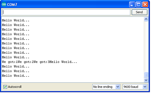
Networking and Communication in Final Project The communication part of the final project, which will involve the communication between mobile devices via Wi-Fi, will be updated when finished. I used the Arduino IDE Serial Monitor which can be evoked by clicking the icon the right-top corner.īy typing in the node number, the console will display the node name and the LED on the corresponding board will blink. When the boards are connected to the computer, they are ready to be tested either with Arduino IDE or PuTTY.
Software serial esp8266 programming code#
PinMode(3, OUTPUT) // open line to writeīy connecting the board with USB cable, we can upload the code to the board. SoftwareSerial mySerial(2,3) // RX, TX (The ATTiny Pin number, NOT the board Pin number)Ĭonst char node = '2' // network addressĬonst int ledPin = 1 // the number of the LED pin I mistakenly used the board Pin number at first and get really strange outcomes.Īfter determining the Pin number, the code for node 2 can be easily revised from the code of node 1. It is important to notice that difference between ATTiny Pin number and the board Pin number. RX : ATTiny412 Pin 4 - Board Pin 5 - UNO 0 (RX).TX : ATTiny412 Pin 3 - Board Pin 4 - UNO 1(TX).VCC: ATTiny412 Pin 0 - Board Pin 3 - UNO 5V.GND: ATTiny412 Pin 8 - Board Pin 1 -UNO GND.Thus, both the ATTiny chip pin structure and how it is connected to the board need to be specified.īased on the structures, in my case, the mapping between the Pins should be:


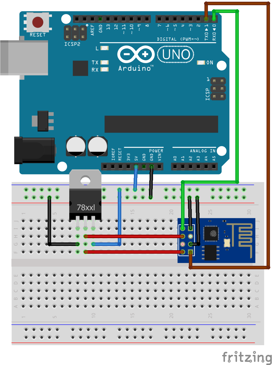
In my case, there are two sets of pincode mapping: (1) between ATTiny and the board and (2) between the board and UNO. This board will be connected to the computer via the Arduino Board, so determining the right Pins to wire is an important procedure. The second step is to program the microcontroller with an ATTiny412. Tool>Board: Arduino UNO >Port: >Programmer: AVRISP mkll>UploadĪrduino UNO board Node 2. In my case, I used the USB cable to connect the Arduino UNO board to the computer. The code are shown as below, which refered to Jari's archive.Ĭonst char node = '1' // network addressĬonst int ledPin = 13 // the number of the LED pin, which is 13 for UNO board The first step is to program the Arduino Uno board to response to input node number. Serial Communication Mechanism Node 1.Arduino Uno board The core mechanism of this type of serial connection is to let the devices share the Tx and Rx input.
Software serial esp8266 programming archive#
This assignment has referred to Jari's archive about this topic. In this week, I decided to simply connect my Arduino UNO board and the microcontroller with an ATTiny412 chip that I made in week 6.


 0 kommentar(er)
